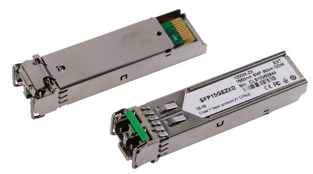

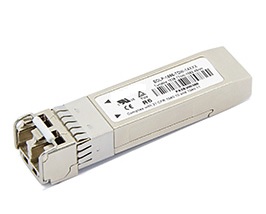
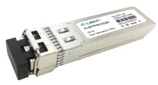
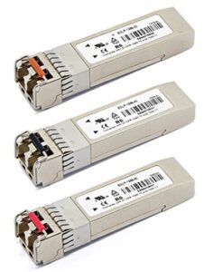
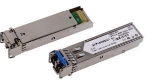
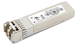
1.25Gbps 1550nm 80KM SFP Transceiver
Model/PN: NASASFP15GEZXD
Product Features
- Up to 1.25Gbps data links
- 80Km with 9/125µm SMF
- 1550nm DFB laser
- Duplex LC Connector
- Hot-pluggable SFP footprint
- Single 3. 3V power supply
- Operating temperature: 0~70°C.
- RoHS
- Digital Diagnostic Monitor (DDM)
Applications
- 25Gbps 1000Base-EX ZX
- 1/2Gbps Fiber Channel
1. Product Description
The NASASFP15GEZXD is a small form factor pluggable (SFP) transceiver module is individually tested on a series of Cisco, Juniper, Dell, HP, IBM…. switches, routers, servers, network interface card (NICs) etc, and is fully compatible with multi-sourcing agreement (MSA). It is suitable for single-mode fiber (SMF) communications in 1.25Gbps Ethernet and 1G/2G Fiber Channel.
2. Regulatory Compliance
NASA-SI transceivers are Class 1 Laser Products comply with FDA regulations. Meet Class 1 eye safety requirements of EN 60825 and the electrical safety requirements of EN 60950.
3. Absolute Maximum Ratings
|
Parameter |
Symbol |
Min. |
Max. |
Unit |
|
Supply Voltage |
VCC |
-0.5 |
3.6 |
V |
|
Storage Temperature |
TS |
-40 |
85 |
°C |
|
CLSFP13GEZXD |
Tc |
0 |
70 |
°C |
4. Recommended Operating Conditions
|
Parameter |
Symbol |
Min. |
Typical |
Max. |
Unit |
|
Power Supply Voltage |
VCC |
3.15 |
3.3 |
3.45 |
V |
|
Power Supply Current |
ICC |
|
|
300 |
mA |
|
Data Rate |
|
|
1.25 |
2.125 |
Gbps |
5. Optical Characteristics
|
Parameter |
Symbol |
Min. |
Typical |
Max. |
Unit |
|
Transmitter |
|||||
|
Centre Wavelength |
λc |
1500 |
1550 |
1570 |
nm |
|
Spectral Width (RMS) |
σ |
|
|
1 |
nm |
|
Average Output Power |
Pout |
0 |
|
5 |
dBm |
|
Extinction Ratio |
EX |
9 |
|
|
dB |
|
Optical Rise/Fall Time |
tr/tf |
|
|
1 |
ns |
|
Receiver |
|||||
|
Centre Wavelength |
λc |
1200 |
|
1600 |
nm |
|
Receiver Sensitivity |
PIN |
|
|
-24 |
dBm |
|
Receiver Overload |
Pmax |
1 |
|
|
dBm |
|
LOS De-Assert |
LOSD |
|
|
-34 |
dBm |
|
LOS Assert |
LOSA |
-37 |
|
|
dBm |
|
LOS Hysteresis |
|
0.5 |
|
4.5 |
dB |
6. Electrical Characteristics
|
Parameter |
Symbol |
Min. |
Typical |
Max. |
Unit |
|
Transmitter |
|||||
|
Input Differential Impedance |
Zin |
90 |
100 |
110 |
Ω |
|
Data Input Swing Differential |
Vin |
500 |
|
2400 |
mV |
|
Tx-Dis Disable |
Vd |
2.0 |
|
Vcc |
V |
|
Tx-Dis Enable |
Ven |
0 |
|
0.8 |
V |
|
TX-Fault (Fault) |
|
2.0 |
|
Vcc+0.3 |
V |
|
TX-Fault (Normal) |
|
0 |
|
0.8 |
V |
|
Receiver |
|||||
|
Data Output Swing Differential |
Vout |
370 |
|
2000 |
mV |
|
Rx-Los Fault |
Vlf |
2.0 |
|
Vcc+0.3 |
V |
|
Rx-Los Normal |
Vln |
0 |
|
0+0.8 |
V |
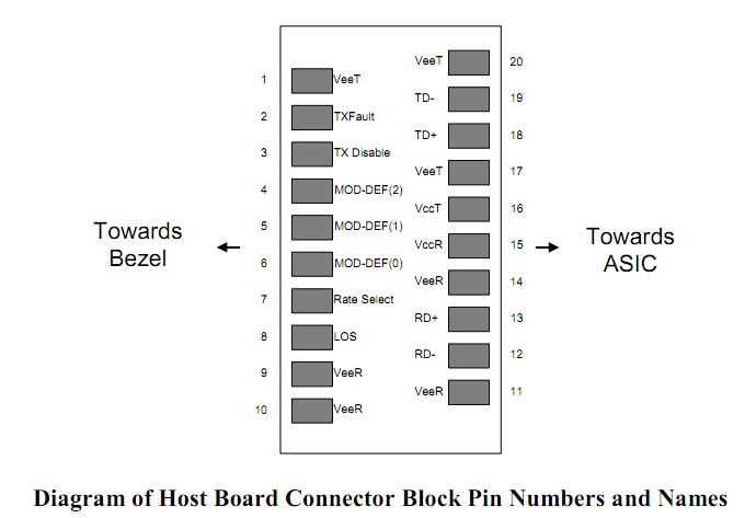
7. Pin Descriptions
|
Pin |
Symbol |
Description |
Ref. |
|
1 |
VEET |
Transmitter Ground (Common with Receiver Ground) |
6.1 |
|
2 |
TFAULT |
Transmitter Fault. Not supported. |
|
|
3 |
TDIS |
Transmitter Disable. Laser output disabled on high or open. |
6.2 |
|
4 |
MOD_DEF(2) |
Module Definition 2. Data line for Serial ID. |
6.3 |
|
5 |
MOD_DEF(1) |
Module Definition 1. Clock line for Serial ID. |
6.3 |
|
6 |
MOD_DEF(0) |
Module Definition 0. Grounded within the module. |
6.3 |
|
7 |
Rate Select |
No connection required |
|
|
8 |
LOS |
Loss of Signal indication. Logic 0 indicates normal operation. |
6.4 |
|
9 |
VEER |
Receiver Ground (Common with Transmitter Ground) |
6.1 |
|
10 |
VEER |
Receiver Ground (Common with Transmitter Ground) |
6.1 |
|
11 |
VEER |
Receiver Ground (Common with Transmitter Ground) |
6.1 |
|
12 |
RD- |
Receiver Inverted DATA out. AC Coupled. |
|
|
13 |
RD+ |
Receiver Non-inverted DATA out. AC Coupled. |
|
|
14 |
VEER |
Receiver Ground (Common with Transmitter Ground) |
6.1 |
|
15 |
VCCR |
Receiver Power Supply |
|
|
16 |
VCCT |
Transmitter Power Supply |
|
|
17 |
VEET |
Transmitter Ground (Common with Receiver Ground) |
6.1 |
|
18 |
TD+ |
Transmitter Non-Inverted DATA in. AC Coupled. |
|
|
19 |
TD- |
Transmitter Inverted DATA in. AC Coupled. |
|
|
20 |
VEET |
Transmitter Ground (Common with Receiver Ground) |
6.1 |
Notes:
7.1 Circuit ground is internally isolated from chassis ground.
7.2 Laser output disabled on TDIS >2.0V or open, enabled on TDIS <0.8V.
7.3 Should be pulled up with 4.7k – 10kohms on host board to a voltage between 2.0V and 3.6V. MOD_DEF(0) pulls line low to indicate module is plugged in.
7.4 LOS is open collector output. Should be pulled up with 4.7k -10kohms on host board to a voltage between 2.0V and 3.6V. Logic 0 indicates normal operation; logic 1 indicates loss of signal.
8. EEPROM & DDM THRESHOLD
8.1 EEPROM
2 wire address 1010000X (A0h)
|
0~95 Serial ID Defined by SFP MSA (96 bytes) |
|
96~127 Vendor Speific (32 bytes) |
|
128~255 Reserved (128 bytes) |
8.2 DDM THRESHOLD
|
|
Low Alarm |
Low Warn |
High Warn |
High Alarm |
|
Temperature |
-5℃ |
0℃ |
70℃ |
75℃ |
|
Voltage |
2.8V |
3.1V |
3.5V |
3.8V |
|
Tx Bias |
-15mA |
-20mA |
40mA |
45mA |
|
Tx Power |
-2dBm |
-1dBm |
6dBm |
7dBm |
|
Rx Power |
-24dBm |
-23dBm |
1dBm |
2dBm |
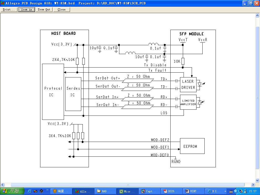
9. Recommend Circuit
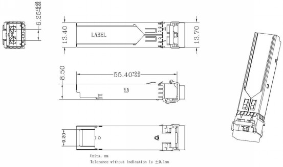
10. Mechanical Specifications
12. Label
NASA-SI offers label OEM design and print.
Label barcode supports code128 and 2D barcode
SIZE: 30mm * 9mm

Ordering Information
|
Part No. |
Data Rate |
DDM |
Wave |
Fiber Type |
Dist. |
Temp. |
Optical Interface |
|
NASASFP15GEZXD |
1.25Gbps |
yes |
1550nm |
SMF |
80Km |
0~70℃ |
LC |
VERSION UPDATE:
|
VERSION NO. |
DATE |
UPDATED INFORMATION |
|
V20131010 |
20131010 |
1. EEPROM& DDM Threshold updated 2. “LABEL” added 3. Ordering information updated 4. Product picture updated |
|
V20161010 |
20161010 |
5. 1. Ordering information updated |
NOTICE: NASA-SI reserves the right to make changes to this product in this specification without notice, in order to improve product performance.


