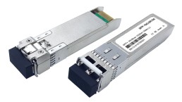
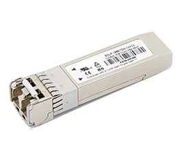
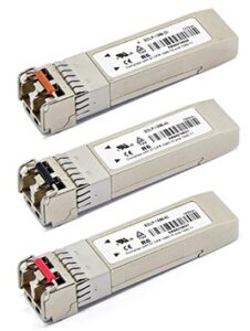
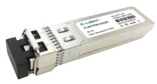
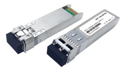
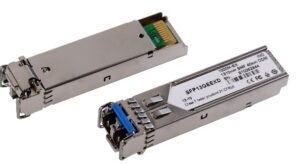
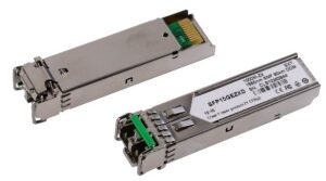
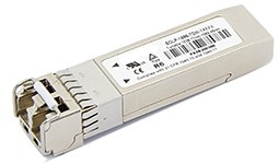
10Gbps 300m SFP+ Transceiver
Model/PN: NASASFPP8510GSR
Features
- • Up to 10Gbps data links
- • 300m with 50/125µm 2000MHz MMF
- • 850nm VCSEL laser
- • Duplex LC Connector
- • Hot-pluggable SFP+ footprint
- • Single 3. 3V power supply
- • Operating temperature: 0℃ to 70℃
- • RoHS
- • Digital Diagnostic Monitor(DDM)
- • Power Consumption < 0.8W
Application
- • 10GBase-SR/SW 10G Ethernet
1. Product Description
NASASFPP8510GSR compatible SFP+ transceiver supports up to 400m link lengths over OM4 MMF (300m over OM3 MMF) via an LC duplex connector. Digital diagnostics monitoring is available via a 2-wire serial interface, as specified in SFF-8472. Each SFP+ transceiver module is individually tested to be used on a series of Cisco, Juniper, Dell, HP, IBM…. switches, routers, servers, network interface card (NICs) etc. Featuring low power consumption, high speed, this 10G SFP+ transceiver is ideal for data center, enterprise wiring closet, service provider transport application, Radio & Baseband Unit, etc.
2. Regulatory Compliance
NASA-SI transceivers are Class 1 Laser Products comply with FDA regulations. Meet Class 1 eye safety requirements of EN 60825 and the electrical safety requirements of EN 60950.
3. Absolute Maximum Ratings
|
Parameter |
Symbol |
Min. |
Max. |
Unit |
|
Supply Voltage |
VCC |
-0.5 |
4 |
V |
|
Storage Temperature |
TS |
-40 |
85 |
°C |
|
Operating Case Temperature |
TC |
0 |
70 |
°C |
4. Recommended Operating Conditions
|
Parameter |
Symbol |
Min. |
Typical |
Max. |
Unit |
|
Operating Case Temperature |
TC |
0 |
|
70 |
°C |
|
Power Supply Voltage |
VCC |
3.15 |
3.3 |
3.45 |
V |
|
Power Supply Current |
ICC |
|
|
200 |
mA |
|
Data Rate |
|
|
10 |
|
GBps |
|
Max Link Length on 50/125µm 2000MHz MMF |
Lmax |
|
|
300 |
m |
5. Optical Characteristics
|
Parameter |
Symbol |
Min. |
Typical |
Max. |
Unit |
|
Transmitter |
|||||
|
Centre Wavelength |
λc |
840 |
850 |
860 |
nm |
|
Spectral Width (RMS) |
σ |
|
|
0.5 |
nm |
|
Average Output Power |
Pout |
-5 |
|
0 |
dBm |
|
Extinction Ratio |
ER |
3.5 |
|
|
dB |
|
Average Launch Power of Off Transmitter |
Poff |
|
|
-30 |
dBm |
|
Receiver |
|||||
|
Centre Wavelength |
λc |
840 |
850 |
860 |
nm |
|
Receiver Sensitivity |
PIN |
|
|
-13 |
dBm |
|
Receiver Overload |
Pmax |
0.5 |
|
|
dBm |
|
LOS De-Assert |
LOSD |
|
|
-16 |
dBm |
|
LOS Assert |
LOSA |
-18 |
|
|
dBm |
|
LOS Hysteresis |
|
0.5 |
|
|
dB |
6. Electrical Characteristics
|
Parameter |
Symbol |
Min. |
Typical |
Max. |
Unit |
|
Transmitter |
|||||
|
Input Differential Impedance |
Zin |
90 |
100 |
110 |
Ω |
|
Data Input Swing Differential |
Vin |
200 |
|
700 |
mV |
|
Tx-Dis Disable |
Vd |
2.0 |
|
Vcc |
V |
|
Tx-Dis Enable |
Ven |
0 |
|
0.8 |
V |
|
Receiver |
|||||
|
Data Output Swing Differential |
Vout |
300 |
|
800 |
mV |
|
Rx-Los Fault |
Vlf |
2.0 |
|
VccHOST |
V |
|
Rx-Los Normal |
Vln |
0 |
|
0+0.8 |
V |
|
Output rise and fall time |
Tr, Tf |
28 |
|
|
ps |
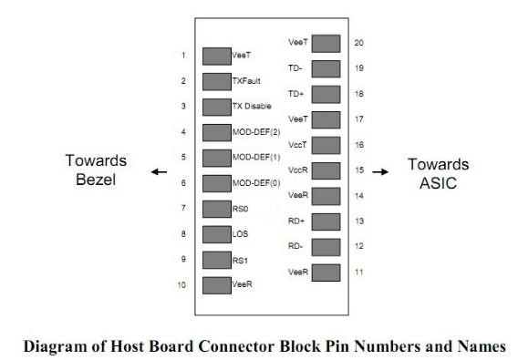
7. Pin Description
Warnings
Handling Precautions: This device is susceptible to damage as a result of electrostatic discharge (ESD). A static free environment is highly recommended. Follow guidelines according to proper ESD procedures.
Laser Safety: Radiation emitted by laser devices can be dangerous to human eyes. Avoid eye exposure to direct or indirect radiation.
8. EEPROM & DDM THRESHOLD
8.1 EEPROM
2 wire address 1010000X (A0h)
|
0~95 Serial ID Defined by SFP MSA (96 bytes) |
|
96~127 Vendor Specific (32 bytes) |
|
128~255 Reserved (128 bytes) |
8.2 DDM THRESHOLD
|
|
Low Alarm |
Low Warn |
High Warn |
High Alarm |
|
Temperature |
-5℃ |
0℃ |
70℃ |
75℃ |
|
Voltage |
3V |
3V |
3.6V |
3.7V |
|
Tx Bias |
4mA |
5mA |
10.8mA |
11.8mA |
|
Tx Power |
-6dBm |
-5dBm |
-1dBm |
0dBm |
|
Rx Power |
-16dBm |
-14dBm |
-1dBm |
0dBm |
9. Mechanical Specifications
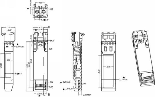
10. Label
NASA-SI offers label OEM design and print.
Label barcode supports code128 and 2D barcode
SIZE: 1) Front 35mm*10.5mm 2)Back 26mm*10.5mm

11. Ordering Information
|
Part No. |
Data Rate |
DDM |
Wave |
Fiber Type |
Dist. |
Temp. |
Optical Interface |
|
NASASFPP8510GSR |
10Gbps |
yes |
850nm |
MMF |
300m |
0~70℃ |
LC |
VERSION UPDATE:
|
VERSION NO. |
DATE |
UPDATED INFORMATION |
|
V20160818 |
20160818 |
1. EEPROM& DDM Threshold updated 2. “LABEL” added 3. Ordering information updated 4. Product picture updated |
NOTICE: NASA-SI reserves the right to make changes to this product in this specification without notice, in order to improve product performance.

