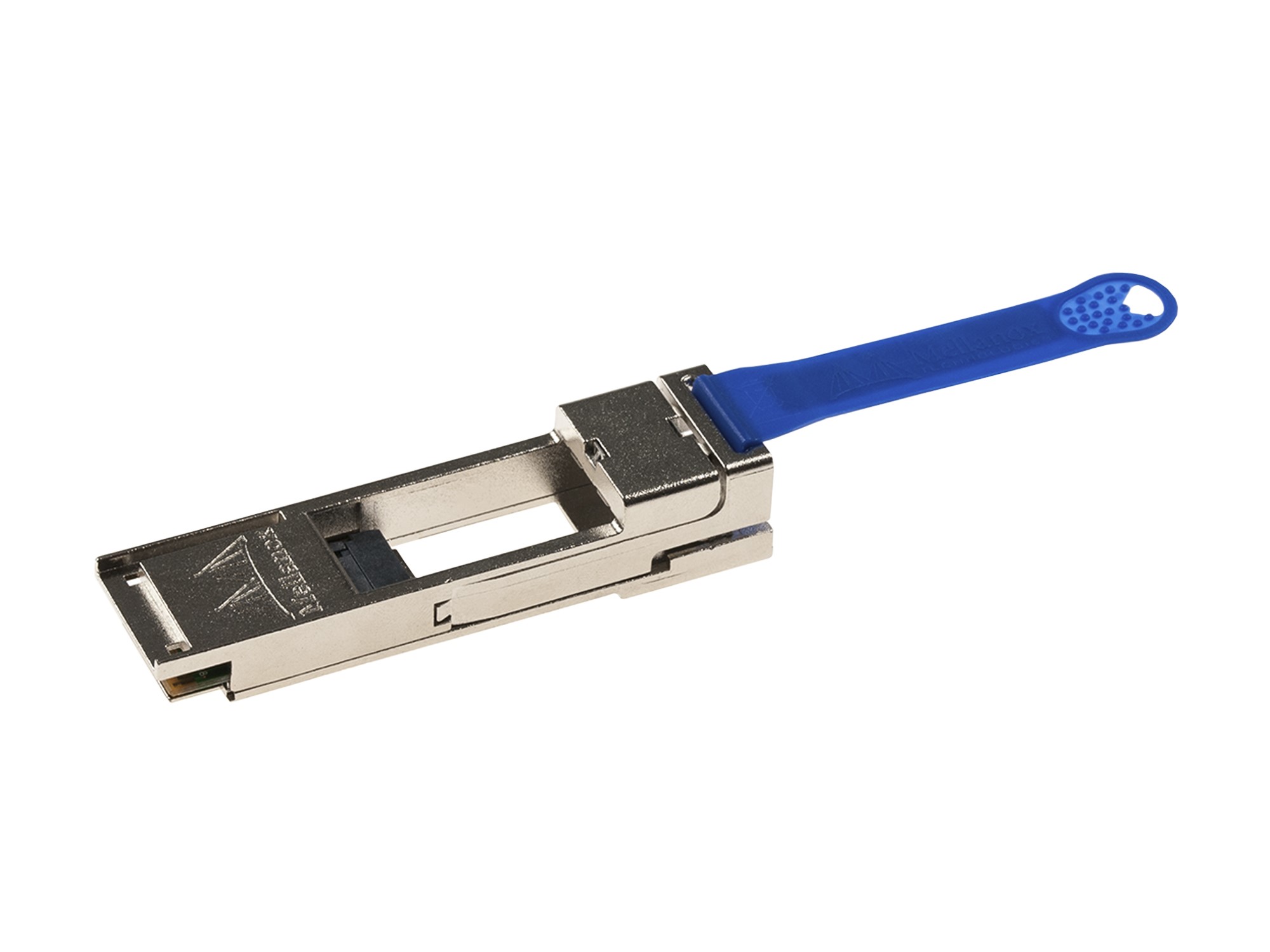
40G QSFP+ to 10G SFP+ Adapter Converter Module
Model/PN: NASACVR-QSFP-SFP10G
Product Features
- • Trouble-free installation and network bring-up
- • Low insertion loss
- • Low crosstalk
- • Secure latching mechanism
- • Operating case temperature: -20 to 85℃
- • 100 ohm differential impedance system
- • Compliant to industry standards : QSFP+ MSA SFF-8436 / SFP+ MSA SFF-8431
- • All-metal housing for superior EMI performance
- • RoHS compliant
- • Precision process control for minimization of pair-to-pair skew
- • 1 independent duplex channels operating at 10Gbps, also support for 2.5Gbps, 5Gbps data rates
Applications
- • Data Servers, Routers, Switches, firewall, …
- • Networked storage systems
- • Data Center networking
- • InfiniBand Trade Association (IBTA)
- • IEEE-802.3baIEEE-802.3bj
- • MSA SFF-8431
1. Product Description
The NASACVR-QSFP-SFP10G Module offers 10 Gigabit Ethernet connectivity for Quad Small Form-Factor Pluggable (QSFP)-only platforms. It allows smooth and cost- effective migration to 40 Gigabit Ethernet by providing an option to use lower-speed Enhanced Small Form-Factor Pluggable (SFP+) modules in empty QSFP ports or when the other end of the network is running at lower speeds.
The NASACVR-QSFP-SFP10G Module is individually tested on corresponding equipment such as Cisco, Palo Alto, Juniper, Dell, HP, IBM, Nokia, Alcatel Lucent…. switches, routers, firewall, servers, network interface card (NICs) etc., and passes the monitoring of NASA-SI intelligent quality control system.
The NASACVR-QSFP-SFP10G Module converts a QSFP port into an SFP+ port. With this adapter, customers have the flexibility to use any SFP+ module or cable to connect to a lower-speed port on the other end of the network. This flexibility allows a cost-effective transition to 40 Gigabit Ethernet by maximizing the use of high-density 40 Gigabit Ethernet QSFP platforms. This adapter supports all SFP+ optics and cable reach. Compatible Switch Models and SFP+ Modules. A list of SFP+ transceiver modules that can be plugged into the QSA module is provided in Table.
|
Item |
Product Name |
Product Description |
|
1 |
SFP-10G-SR |
10GBASE-SR SFP+ Module for Multimode Fiber |
|
2 |
SFP-10G-LR |
10GBASE-LR SFP+ Module for Single-Mode Fiber |
|
3 |
SFP-10G-ER |
10GBASE-ER SFP+ Module for Single-Mode Fiber |
|
4 |
SFP-10G-ZR |
DWDM SFP+ Modules for Single-Mode Fiber |
|
5 |
10G SFP+ Copper Cables |
SFP+ Copper Cables (1 -m to 10-m lengths) |
|
6 |
10G SFP+ Active Optical Cables |
SFP+ Active Optical Cables (1-m to 10-m lengths) |
2. Absolute Maximum Ratings
|
Parameter |
Symbol |
Min. |
Max. |
Unit |
|
Supply Voltage |
VCC |
-0.5 |
4 |
V |
|
Storage Temperature |
TS |
-40 |
85 |
°C |
|
Operating Case Temperature |
TC |
-40 |
85 |
°C |
3. Recommended Operating Conditions
|
Parameter |
Symbol |
Min. |
Typical |
Max. |
Unit |
|
Operating Case Temperature |
Topc |
-20 |
40 |
85 |
degC |
|
Storage Temperature |
Tst |
-40 |
|
125 |
degC |
|
Relative Humidity (non-condensation) |
RS |
– |
|
85 |
% |
|
Supply Voltage |
VCC3 |
3.15 |
|
3.45 |
v |
4. Optical Characteristics QSFP+ Host Board Connector Pinout
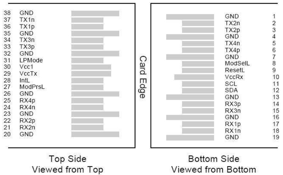
Figure 1: MSA Compliant Connector
Pin Definitions
|
Pin |
Logic |
Symbol |
Name/Description |
Note |
|
1 |
|
GND |
Ground |
1 |
|
2 |
CML-I |
Tx2n |
Transmitter Inverted Data Input |
|
|
3 |
CML-I |
Tx2p |
Transmitter Non-Inverted Data output |
|
|
4 |
|
GND |
Ground |
1 |
|
5 |
CML-I |
Tx4n |
Transmitter Inverted Data Input |
|
|
6 |
CML-I |
Tx4p |
Transmitter Non-Inverted Data output |
|
|
7 |
|
GND |
Ground |
1 |
|
8 |
LVTLL-I |
ModSelL |
Module Select |
|
|
9 |
LVTLL-I |
ResetL |
Module Reset |
|
|
10 |
|
VccRx |
+ 3.3V Power Supply Receiver |
2 |
|
11 |
LVCMOS-I/O |
SCL |
2-Wire Serial Interface Clock |
|
|
12 |
LVCMOS-I/O |
SDA |
2-Wire Serial Interface Data |
|
|
13 |
|
GND |
Ground |
1 |
|
14 |
CML-O |
Rx3p |
Receiver Non-Inverted Data Output |
|
|
15 |
CML-O |
Rx3n |
Receiver Inverted Data Output |
|
|
16 |
|
GND |
Ground |
1 |
|
17 |
CML-O |
Rx1 p |
Receiver Non-Inverted Data Output |
|
|
18 |
CML-O |
Rx1 n |
Receiver Inverted Data Output |
|
|
19 |
|
GND |
Ground |
1 |
|
20 |
|
GND |
Ground |
1 |
|
21 |
CML-O |
Rx2n |
Receiver Inverted Data Output |
|
|
22 |
CML-O |
Rx2p |
Receiver Non-Inverted Data Output |
|
|
23 |
|
GND |
Ground |
1 |
|
24 |
CML-O |
Rx4n |
Receiver Inverted Data Output |
1 |
|
25 |
CML-O |
Rx4p |
Receiver Non-Inverted Data Output |
|
|
26 |
|
GND |
Ground |
1 |
|
27 |
LVTTL-O |
ModPrsL |
Module Present |
|
|
28 |
LVTTL-O |
IntL |
Interrupt |
|
|
29 |
|
VccTx |
+3.3 V Power Supply transmitter |
2 |
|
30 |
|
Vcc1 |
+3.3 V Power Supply |
2 |
|
31 |
LVTTL-I |
LPMode |
Low Power Mode |
|
|
32 |
|
GND |
Ground |
1 |
|
33 |
CML-I |
Tx3p |
Transmitter Non-Inverted Data Input |
|
|
34 |
CML-I |
Tx3n |
T ransmitter Inverted Data Output |
|
|
35 |
|
GND |
Ground |
1 |
|
36 |
CML-I |
Tx1 p |
Transmitter Non-Inverted Data Input |
|
|
37 |
CML-I |
Tx1 n |
T ransmitter Inverted Data Output |
|
|
38 |
|
GND |
Ground |
1 |
Note:
1. GND is the symbol for signal and supply (power) common for QSFP modules. All are common within the QSFP module and all module voltages are referenced to this potential otherwise noted. Connect these directly to the host board signal common ground plane 2.cc Rx, Vcc1 and Vcc Tx are the receiver and transmitter power suppliers and shall be applied concurrently. Recommended host board power supply filtering is shown below. Vcc Rx, Vcc1 and Vcc Tx may be internally connected within the QSFP transceiver module in any combination. The connector pins are each rated for a maximum current of 500mA.
5. Electrical Characteristics SFP+ Host Board Connector Pinout for SFP+
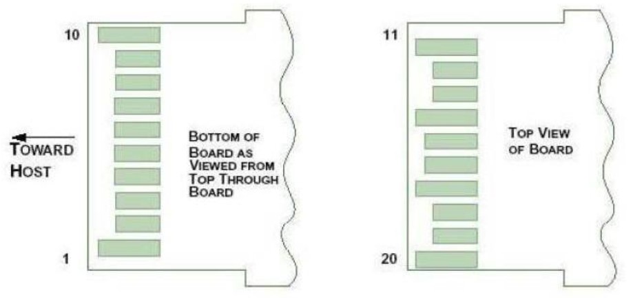
Figure 2: MSA Compliant Connector
Pin Definitions
|
Pin |
Logic |
Symbol |
Name/Description |
Note |
|
1 |
|
VeeT |
Module T ransmitter Ground |
1 |
|
2 |
LVTTL-O |
Tx_Fault |
Transmitter Fault |
2 |
|
3 |
LVTTL-I |
Tx_Disable |
Transmitter Disable |
3 |
|
4 |
LVTTL-I/O |
SDA |
MOD-DEF2 2-wire serial interface data line |
4 |
|
5 |
LVTTL-I/O |
SCL |
MOD-DEF1 2-wire serial interface clock line |
4 |
|
6 |
|
Mod_Abs |
Module Absent |
5 |
|
7 |
LVTTL-I |
RS0 |
Rate Select Zero |
|
|
8 |
LVTTL- O |
Rx_LOS |
Module Receiver Loss of Signal |
2 |
|
9 |
LVTTL-I |
RS1 |
Rate Select One |
|
|
10 |
|
VeeR |
Module Receiver Ground |
1 |
|
11 |
|
VeeR |
Module Receiver Ground |
1 |
|
12 |
CML-O |
RD- |
Receiver Inverted Data Output |
|
|
13 |
CML-O |
RD+ |
Receiver Non-Inverted Data Output |
|
|
14 |
|
VeeR |
Module Receiver Ground |
1 |
|
15 |
|
VccR |
Module Receiver 3.3V Supply |
|
|
16 |
|
VccT |
Module Transmitter 3.3V Supply |
|
|
17 |
|
VeeT |
Module Transmitter Ground |
1 |
|
18 |
CML-I |
TD+ |
Transmitter Non-Inverted Data Input |
|
|
19 |
CML-I |
TD- |
Transmitter Inverted Data Input |
|
|
20 |
|
VeeT |
Module Transmitter Ground |
1 |
Notes:
- The module signal grounds, VeeR and VeeT, shall be isolated from the module case.
- This is an open collector/drain output and shall be pulled up with 4.7-10k to Vcc_Host on the host board. Pull ups can be connected to multiple power supplies, however the host board design shall ensure that no module has voltage exceeding module VccT/R + 0.5 V.
- This is an open collector/drain input and shall be pulled up with 4.7-10k to VccT in the module.
- See 2-wire electrical specifications.
- This shall be pulled up with 4.7-10k to Vcc_Host on the host board
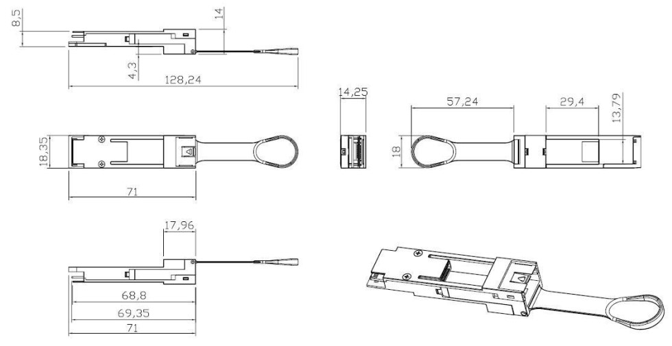
6. Mechanical Dimensions
7. Label
NASA-SI offers label OEM design and print.
Label barcode supports code128 and 2D barcode
SIZE: 1) Front 35mm*10.5mm 2)Back 26mm*10.5mm

8. Ordering Information
|
Part No. |
Data Rate |
|
NASACVR-QSFP28-SFP28 |
100G QSFP28 to 25G SFP28 Adapter Converter Module |
|
NASACVR-QSFP-SFP10G |
40G QSFP+ to 10G SFP+ Adapter Converter Module |
NOTICE: NASA-SI reserves the right to make changes to this product in this specification without notice, in order to improve product performance.

